Adding senses to your Arduino
- Sep 18, 2021
- 11 min read
Updated: Mar 6, 2022
“If you want your Arduino to sense the world around it, you will need to add a sensor.“
But unlike us humans who have just 5 basic senses, a microcontroller can have 1000+ senses with the help of sensors.
What is a Sensor?
The sensors are defined as a machine, module, or device that detects changes in the environment. The sensors transfer those changes to the electronic devices in the form of a signal. A sensor and electronic devices always work together and produce an output signal which can be converted into a human-readable form.
Where are the sensors used?
The sensors are used to measure the physical quantities, such as pressure, temperature, sound, humidity, and light, etc. An example of a sensor is Fire Alarm, a detector present on the fire alarm detects smoke or heat.
The signal generated from the detector is sent to the alarming system, which produces an alert in the form of an alarm. The types of detectors are smoke detectors, heat detectors, carbon monoxide detectors, multi-sensors detectors, etc.
Few examples of sensors are Ultrasonic Sensor, IR Sensor, DHT Sensor, Photoresistor Sensor, etc.

Deep diving into sensors
Ultrasonic Sensor
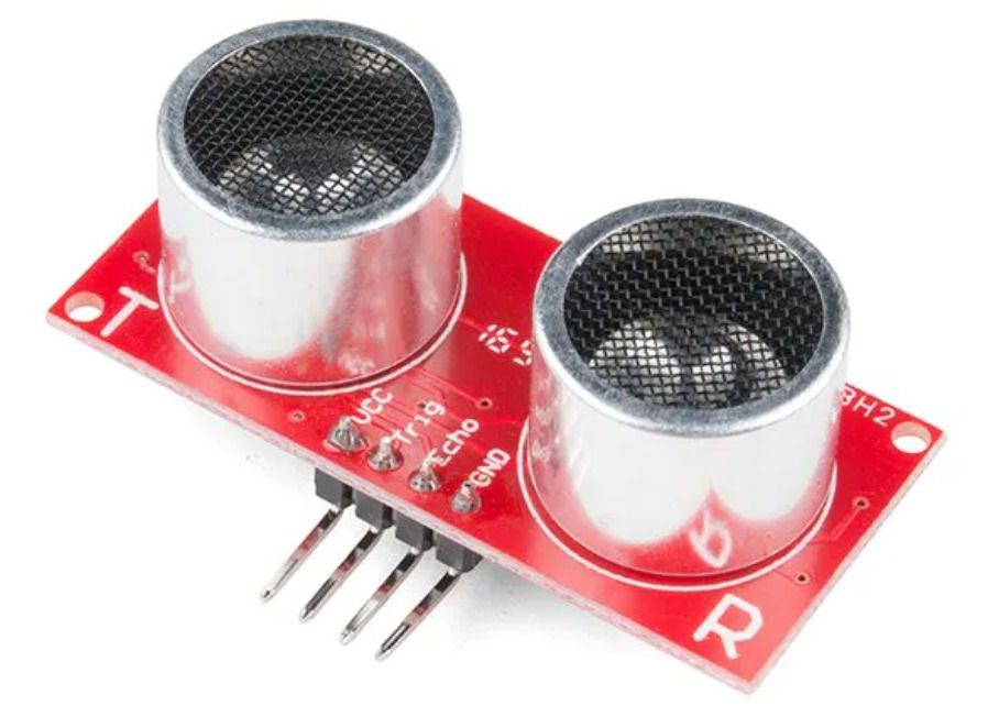
An ultrasonic sensor is an electronic device that measures the distance of a target object by emitting ultrasonic sound waves and converts the reflected sound into an electrical signal. Ultrasonic waves travel faster than the speed of audible sound (i.e. faster than 20kHz).
Ultrasonic sensors have two main components: the transmitter (which emits the sound using piezoelectric crystals) and the receiver (which encounters the sound after it has traveled to and from the target). It emits ultrasound at 40kHz which travels through the air and if there is any obstacle on its path, it will bounce back towards the module. Considering the travel time and the speed of the sound you can calculate the distance.
Specs:
Nominal Frequency output: 40 kHz.
Coverage range: 0.2 to 6 meters
Receiver sensitivity: -67 dBm
Sound pressure level: 112 dB (minimum)
Maximum voltage input: 20 V(RMS)
Connection of Arduino and Ultrasonic Sensor HC-SR04:
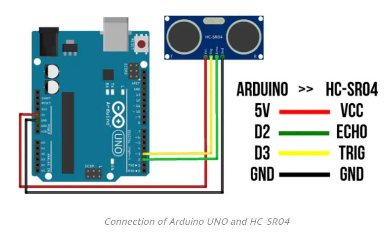
To generate the ultrasonic sound waves, we need to set the Trigger Pin on a High State for 10 µs. That will send out an 8 cycle sonic burst which will travel at the speed sound and it will be received in the Echo Pin. The Echo Pin will output the time in microseconds the sound wave traveled.
For example, if the object is 20 cm away from the sensor, and the speed of the sound is 340 m/s or 0.034 cm/µs the sound wave will need to travel about 588 microseconds. But what you will get from the Echo pin will be double that number because the sound wave needs to travel forward and bounce backward. So to get the distance in cm, we need to multiply the received travel time value from the echo pin by 0.034 and divide it by 2.
distance = (duration * 0.034) / 2
Code Explanation:
Define the Trigger Pin and Echo Pin that are connected to the Arduino board.
EchoPin is attached to D2 and TrigPin to D3.
Define variables for the distance (int) and duration (long).
In the loop first, you have to make sure that the trigPin is clear so we have to set that pin on a LOW State for just 2 µs. Now for generating the ultrasound wave we have to set the trigPin on HIGH State for 10 µs.
Using the pulseIn()function you have to read the travel time and put that value into the variable “duration”. This function has 2 parameters, the first one is the name of the echo pin and for the second one, you can write either HIGH or LOW.
In this case, HIGH means that the pulseIn() function will wait for the pin to go HIGH caused by the bounced sound wave and it will start timing, then it will wait for the pin to go LOW when the sound wave will end which will stop the timing. In the end, the function will return the length of the pulse in microseconds.
For getting the distance we will multiply the duration by 0.034 and divide it by 2.
Before reading the code, try to write it on your own 👩💻.

Check with the circuit diagram and try again. If you still don’t get the output, check with the code below.
Code:
#define echoPin 2 // attach pin D2 Arduino to pin Echo of HC-SR04
#define trigPin 3 //attach pin D3 Arduino to pin Trig of HC-SR04

// defines variables
long duration; // variable for the duration of sound wave travel
int distance; // variable for the distance measurement

void setup() {
  pinMode(trigPin, OUTPUT); // Sets the trigPin as an OUTPUT
  pinMode(echoPin, INPUT); // Sets the echoPin as an INPUT
  Serial.begin(9600); // Serial Communication is starting with 9600 of baud rate speed
  Serial.println("Ultrasonic Sensor HC-SR04 Test"); // print some text in Serial Monitor
  Serial.println("with Arduino UNO R3");
}

void loop() {
  // Clears the trigPin condition
  digitalWrite(trigPin, LOW);
  delayMicroseconds(2);

  // Sets the trigPin HIGH (ACTIVE) for 10 microseconds
  digitalWrite(trigPin, HIGH);
  delayMicroseconds(10);
  digitalWrite(trigPin, LOW);

  // Reads the echoPin, returns the sound wave travel time in microseconds
  duration = pulseIn(echoPin, HIGH);

  // Calculating the distance
  distance = duration * 0.034 / 2; // Speed of sound wave divided by 2 (go and back)

  // Displays the distance on the Serial Monitor
  Serial.print("Distance: ");
  Serial.print(distance);
  Serial.println(" cm");
}
ARDUINO IDE
Make the connections as shown in the figure
Open Arduino IDE Software and write down your code.
Choose your own Arduino board (in this case Arduino Uno), by selecting Tools > Board > Arduino Uno.
Choose your COM Port (usually it appears only one existing port), Tools > Port > COM.. (If there is more than one port, try it one by one)
Upload your code by pressing Ctrl + U or Sketch > Upload
To display the measurement data you can use Serial Monitor by pressing Ctrl + Shift + M (make sure that the baud rate speed is 9600)
After uploading the code, display the data with Serial Monitor. Now try to give an object in front of the sensor and see the measurement.
TINKERCAD
Click on ‘create new circuit’ to make a new circuit 🛠.
On the right side, a list of components will be available. Search for ‘Arduino Uno’ and ‘Ultrasonic Distance Sensor’ in that search bar to find the ‘Arduino Uno R3’ board and the Sensor.
Drag and drop in the white open area.
Make the connections as shown in the figure.
Go to the ‘code’ tab from the tabs available to the top right and click on it.
Change the edit mode from blocks to text.
Write the code and click on “Start Simulation”
Click on the sensor then you can see a ball (kind of obstacle) which also shows the distance between the obstacle and the sensor.
IR SENSOR
IR sensor is a type of sensor which uses Infrared waves or light to detect the object placed ahead of it. Since this sensor uses Infrared waves to detect the object, it is called an Infrared sensor.
Just like visible light, Infrared wave/light is part of the electromagnetic spectrum. But unlike sunlight/visible light, the human eye cannot see IR waves. Although it can be detected as heat.
You may not be aware that you encounter Infrared waves every day. For example, a TV remote uses light waves just beyond the visible spectrum of light—infrared light waves—to change channels on your TV. Ir sensor uses the same waves to detect the obstacle.
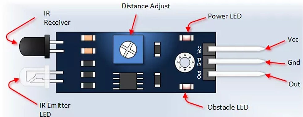
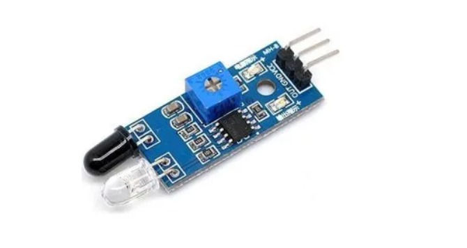
Board layout of an IR Sensor
Every IR Sensor or Infrared Sensor has two main parts. IR Transmitter and IR Receiver. The work of an IR transmitter or Infrared transmitter is to transmit the infrared waves.
Whereas the work of the IR receiver is to receive these transmitted infrared waves. IR receiver constantly sends digital data in the form of 0 or 1 to the Vout pin of the sensor. The single potentiometer on most of the IR sensors is used to set the sensitivity of the sensor or the distance up to which it detects the obstacle. So by rotating the potentiometer you can set the detection distance. There are generally two LEDs on the IR sensor, one is a power indicator and the other one is the output/obstacle indicator.
Different versions of IR sensor:
Now depending upon the number of Pins and potentiometer you may come across different versions of Ir Sensor.
- IR Sensor with three pins:
The IR sensor with three pins has the following pinout: Power pin, Ground pin, and digital output pin. The digital output pin provides data in digital form i.e. 0(HIGH) or 1(HIGH)
- IR sensor with four pins(Output type):
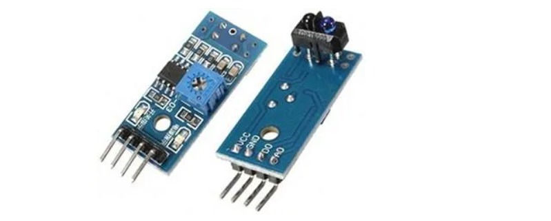
The IR sensor with four pins has the following pinout: Power pin, Ground pin, digital output, and analog output pin. The analog output pin provides data in analog form i.e. between 0 volts and 5 volts(voltage at power pin)
- IR sensor with four pins(Enabling/disabling):
There is another form of IR sensor with 4 pins. This IR sensor has the following pinout: Power pin, Ground pin, digital output pin, and Enable pin. The enable pin is used to enable/disable the IR sensor output.
- IR sensor with Single potentiometer:
The single potentiometer on most of the IR sensors is used to set the sensitivity of the sensor or the distance up to which it detects the obstacle. So by rotating the potentiometer you can set the detection distance.
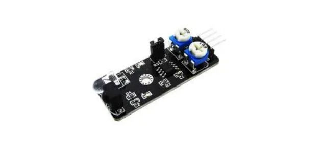
- IR sensor with Two potentiometers:
The second potentiometer is used to set the frequency of IR waves transmission.
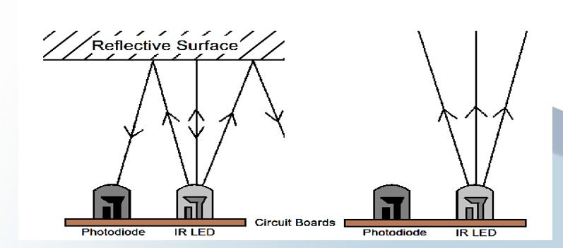
Working of an IR Sensor:
If there is an object in front of the IR sensor, the transmitted infrared waves from the IR transmitter reflect from that object and are received by the IR receiver. IR sensor gives 0 in this condition. Similarly, if there is a white surface in front of the sensor, the IR waves are reflected back from the surface(the white surface does not absorb any light). When there is no object in front of the IR sensor, the transmitted infrared waves from the IR transmitter are not received by the IR receiver then the IR sensor gives 1 in this condition.
Similarly, if there is a black surface in front of the sensor, the IR waves are not reflected back from the surface(the black surface absorbs the light completely).
Circuit Connections:

Before reading the code, try to write it on your own 👩💻.
Code:
int ledPin = 11; int irPin=7;

void setup() {
  pinMode(ledPin, OUTPUT);
  pinMode(irPin,INPUT);
Serial.begin(9600);
}

void loop() {
  if (digitalRead(irPin)==LOW)
  {
    digitalWrite(ledPin,HIGH);
  }
else
  {
    digitalWrite(ledPin,LOW);
  }
}
Applications:
Television remote control
Safety alarm systems
As Proximity sensors in mobile phones
Motion detector
Product counter
DHT11 SENSOR
The DHT11 temperature and humidity Sensor make it really easy to add humidity and temperature data to your DIY electronics projects. The DHT11 is a basic, ultra low-cost digital temperature and humidity sensor. It uses a capacitive humidity sensor and a thermistor to measure the surrounding air and spits out a digital signal on the data pin (no analog input pins needed). It's fairly simple to use but requires careful timing to grab data. The only real downside of this sensor is you can only get new data from it once every 2 seconds, the sensor readings can be up to 2 seconds old.
Compared to DHT22, this sensor is less precise, less accurate, and works in a smaller range of temperature/humidity, but it is smaller and less expensive.
Here are the ranges and accuracy of the DHT11:
Humidity Range: 20-90% RH
Humidity Accuracy: ±5% RH
Temperature Range: 0-50 °C
Temperature Accuracy: ±2% °C
Operating Voltage: 3V to 5.5V
The DHT11 measures relative humidity. The relative humidity is the amount of water vapor in air vs. the saturation point of water vapor in the air. At the saturation point, water vapor starts to condense and accumulate on surfaces forming dew.
The saturation point changes with air temperature. Cold air can hold less water vapor before it becomes saturated, and hot air can hold more water vapor before it becomes saturated.
The formula to calculate relative humidity is:
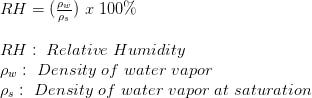
The relative humidity is expressed as a percentage. At 100% RH, condensation occurs, and at 0% RH, the air is completely dry.
Two Versions of DHT11:
There are two different versions of the DHT11 you might come across. One type has four pins, and the other type has three pins and is mounted to a small PCB. The PCB-mounted version is nice because it includes a surface-mounted 10K Ohm pull-up resistor for the signal line. A 10K Ohm pull-up resistor is needed between the signal line and 5V line to make sure the signal level stays high by default. The DHT11 uses just one signal wire to transmit data to the Arduino. Power comes from separate 5V and ground wires.

Setting up the DHT11 on an Arduino board:
Wiring the DHT11 to the Arduino is really easy, but the connections are different depending on which type you have.
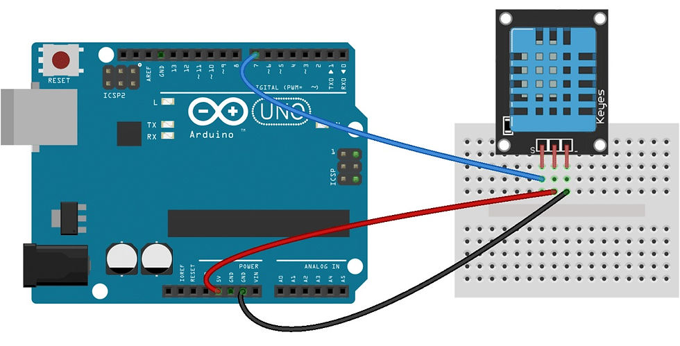
VCC - Connect Red Wire to the 5V Power
Signal - Connect it to Pin Number 7
Ground - Connect it to ground Pin
Arduino IDE:
Open the Arduino IDE
Before writing the code, it’s necessary to install the DHT Sensor library, which can be done through the Arduino Library Manager
Sketch→Include Library→Manage Libraries…
Enter “DHT” in the search field and look through the list for the “DHT sensor library by Adafruit.” Click the “Install” button, or “Update” from an earlier version.
IMPORTANT: As of version 1.3.0 of the DHT library you will also need to install the Adafruit_Sensor library, which is also available in the Arduino Library Manager.
Now load up the Examples→DHT→DHTtester sketch.
Code:
#include <dht.h>
dht DHT;
#define DHT11_PIN 7

void setup(){
  Serial.begin(9600);
}

void loop(){
  int chk = DHT.read11(DHT11_PIN);
  Serial.print("Temperature = ");
  Serial.println(DHT.temperature);
  Serial.print("Humidity = ");
  Serial.println(DHT.humidity);
  delay(1000);
}
You should see the humidity and temperature readings displayed at one-second intervals
Applications:
Remote weather stations
farm or garden monitoring systems.
home environmental control systems
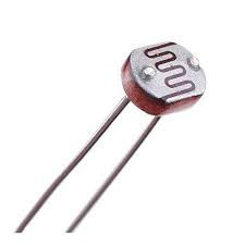
Light Dependent Resistor (LDR) or Photoresistor:
Light Dependent Resistors are the key to building automated lighting. The LDR is an electronic component whose resistivity varies according to the amount of light received ( the resistance decreases when exposed to the light ). It is made of cadmium sulfide tape, a semiconductor. When photons hit the tapes, electrons can pass through the semiconductor. The main use of the photoresistor is the measurement of the luminous intensity ( camera, detection systems, … ).
Working of LDR:
A photoresistor is made of a high resistance semiconductor. In the dark, a photoresistor can have a resistance as high as several megohms (MΩ), while in the light, a photoresistor can have a resistance as low as a few hundred ohms. If incident light on a photoresistor exceeds a certain frequency, photons absorbed by the semiconductor give bound electrons enough energy to jump into the conduction band. The resulting free electrons (and their hole partners) conduct electricity, thereby lowering resistance.
We’ll pair an LDR with an Arduino Uno to demonstrate how they operate together.
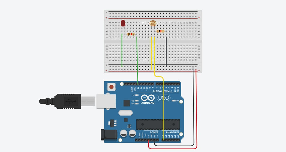
Controlling Led with LDR Sensor:
Led will glow up when it is dark. Energy is saved by ensuring the light is only ON during hours of darkness.
Circuit Diagram:
Make the connections as shown in the figure.
Before reading the code, try to write it on your own 👩💻.
Code:
int LDR= A0; //Set A0(Analog Input) for LDR
int LED = 13;
int value=0;

void setup()
{
  pinMode(LED,OUTPUT);
  Serial.begin(9600);
}

void loop()
{
  value= analogRead(LDR);//Reads the Value of LDR(light).
    if (value<400)
    {
        digitalWrite(LED,HIGH);//Makes the LED glow in Dark.
    }
    else
    {
       digitalWrite(LED,LOW);//Turns the LED OFF in Light.
    }
    Serial.println(value); //Prints the value of LDR to Serial Monitor.
    delay(200);
}
Applications:
Light Sensor - The led lights up when the intensity of the light reaching the LDR resistor is sufficient. Eg: Automatic Emergency Light
Audio Compressor
Fire Alarm
Relay:
A Relay is a programmable electrical switch, which can be controlled by an Arduino or any other microcontroller. It is used to programmatically control on/ off the devices, which use the high voltage and/or high current. It is a bridge between Arduino and high voltage devices.
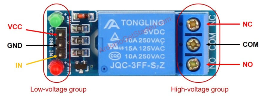
Pins in the low voltage group are connected to Arduino
GND pin: needs to be connected to GND( 0 V).
VCC pin: needs to be connected to GND (5 V).
IN pin: receives a control signal from Arduino
Pins in the high voltage group are connected to a high voltage device
COM pin: known as a common pin, used in both normally open mode and normally closed mode
NO pin: is normally open pin, used in normally open mode.
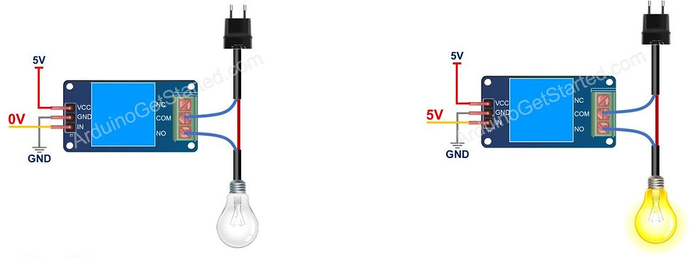
Normally Open Mode:
To use this mode, we need to connect the high voltage device to the COM pin and NO pin.
If the IN pin is connected to LOW (0V), the switch is open and the device is off.
If the IN pin is connected to HIGH (5V), the switch is closed and the device is on.
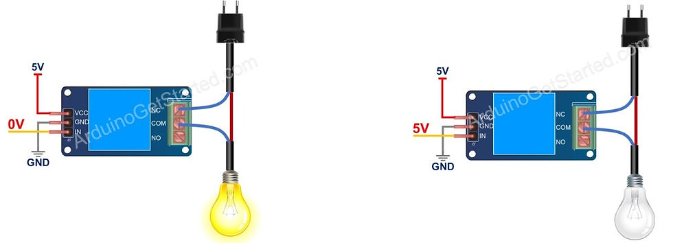
NC pin: is normally closed pin, used in normally closed mode.
Normally Close Mode:
To use this mode, we need to connect the high voltage device to the COM pin and NC pin.
If the IN pin is connected to LOW (0V), the switch is closed and the device is on.
If the IN pin is connected to HIGH (5V), the switch is open and the device is off.
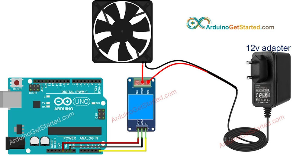
Let us write some code on how to turn on/off the fan using relay and Arduino.
Circuit Diagram:
To turn on turn on/off the fan, we need to use a relay between the Arduino and the fan.
Arduino can turn on/off the fan via the relay.
Code:
const int RELAY_PIN = A5;  // the Arduino pin, which connects to the IN pin of relay

// the setup function runs once when you press reset or power the board
void setup() {
  // initialize digital pin A5 as an output.
  pinMode(RELAY_PIN, OUTPUT);
}

// the loop function runs over and over again forever
void loop() {
  digitalWrite(RELAY_PIN, HIGH); // turn on fan 5 seconds
  delay(5000);
  digitalWrite(RELAY_PIN, LOW);  // turn off fan 5 seconds
  delay(5000);
}
Applications:
Relays are used for isolating a low voltage circuit from a high voltage circuit.
They are used for controlling multiple circuits.
They are also used as automatic changeover.
Microprocessors use relays to control a heavy electrical load.
Overload relays are used for the protection of motors from overload & electrical failure.
Tinker with these sensors, make different circuits, tweak the code and get unique outputs. As an added task, find out the difference between Raspberry PI and Arduino and explore the powers of each.

Follow us on Instagram for updates, event announcements, and regular quizzes to check your understanding.

Comments