Interfacing with the Arduino
- Oct 11, 2021
- 9 min read
Updated: Mar 6, 2022
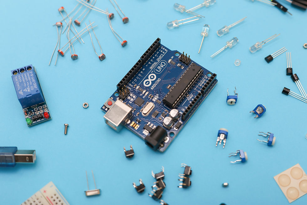
"The Arduino can’t do much on its own. Its purpose is to communicate with external hardware and to control."
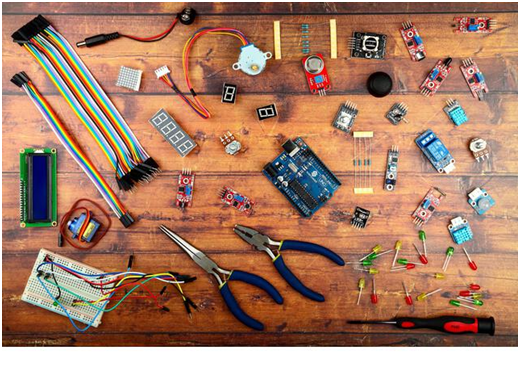
There are many different kinds of hardware that you can connect to the Arduino. And there are a lot of them!
DC MOTORS
In today’s industrial sector, direct current (DC) motors are everywhere. From robotics to automobiles, small and medium-sized motoring applications often feature DC motors for their wide range of functionality.
Because DC motors are deployed in such a wide variety of applications, there are different types of DC motors suited to different tasks across the industrial sector.
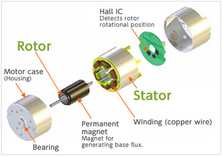
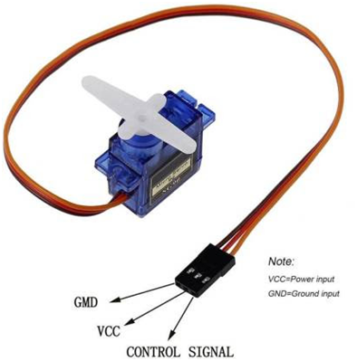
A DC motor (Direct Current motor) is the most common type of motor. DC motors normally have just two leads, one positive and one negative. If you connect these two leads directly to a battery, the motor will rotate. If you switch the leads, the motor will rotate in the opposite direction. It has two wires:
a. Red Wire: Voltage wire that can be i. wired into the 5V turning the motor on with no off switch unless a switch is wired in front of it ii. wired to a digital port, allowing the user to turn the motor on and off using
b. Black Wire: Ground Wire Motor Movement
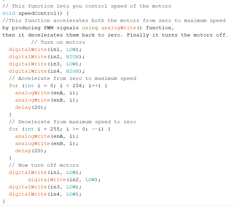
Controlling a DC Motor
To have complete control over the DC motor, we have to control its speed and rotation direction. This can be achieved by combining these two techniques.
PWM – For controlling speed
H-Bridge – For controlling rotation direction
PWM – For controlling speed
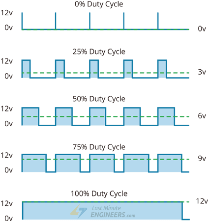
The speed of a DC motor can be controlled by varying its input voltage. A common technique for doing this is to use PWM (Pulse Width Modulation)
PWM is a technique where the average value of the input voltage is adjusted by sending a series of ON-OFF pulses.
The average voltage is proportional to the width of the pulses known as the Duty Cycle.
The higher the duty cycle, the greater the average voltage being applied to the dc motor(High Speed), and the lower the duty cycle, the less the average voltage being applied to the dc motor(Low Speed).
The below image illustrates the PWM technique with various duty cycles and average voltages.
H-Bridge – For controlling rotation direction
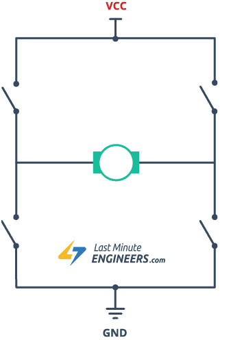
The DC motor’s spinning direction can be controlled by changing the polarity of its input voltage. A common technique for doing this is to use an H-Bridge.
An H-Bridge circuit contains four switches with the motor at the center forming an H-like arrangement.
Closing two particular switches at the same time reverse the polarity of the voltage applied to the motor. This causes a change in the spinning direction of the motor.
The below animation illustrates the H-Bridge circuit working.

L298N Motor Driver IC
The L298N is a dual-channel H-Bridge motor driver capable of driving a pair of DC motors. That means it can individually drive up to two motors making it ideal for building two-wheel robot platforms.

The L298N motor driver module is powered through 3-pin 3.5mm-pitch screw terminals. It consists of pins for motor power supply(Vs), ground, and 5V logic power supply(Vss).
The L298N motor driver’s output channels for motors A and B are broken out to the edge of the module with two 3.5mm-pitch screw terminals.
You can connect two DC motors having voltages between 5 to 35V to these terminals.
Control Pins
For each of the L298N’s channels, there are two types of control pins that allow us to control the speed and spinning direction of the DC motors at the same time viz. Direction control pins & Speed control pins.
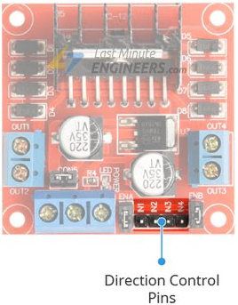
Direction Control Pins
Using the direction control pins, we can control whether the motor spins forward or backward. These pins control the switches of the H-Bridge circuit inside L298N IC.
The module has two direction control pins for each channel. The IN1 and IN2 pins control the spinning direction of motor A while IN3 and IN4 control motor B.
The spinning direction of a motor can be controlled by applying either a logic HIGH(5 Volts) or logic LOW(Ground) to these inputs. The below chart illustrates how this is done.
Input1 Input2 Spinning Direction
Low(0) Low(0) Motor OFF
High(1) Low(0) Forward
Low(0) High(1) Backward
High(1) High(1) Motor OFF
Speed Control Pins

The speed control pins viz. ENA and ENB are used to turn the motors ON, OFF and control their speed.
Pulling these pins HIGH will make the motors spin, pulling them LOW will make them stop. But, with Pulse Width Modulation (PWM), we can control the speed of the motors.
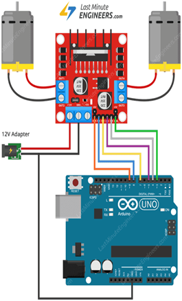
CIRCUIT DIAGRAM:
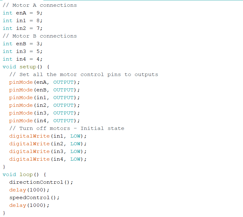
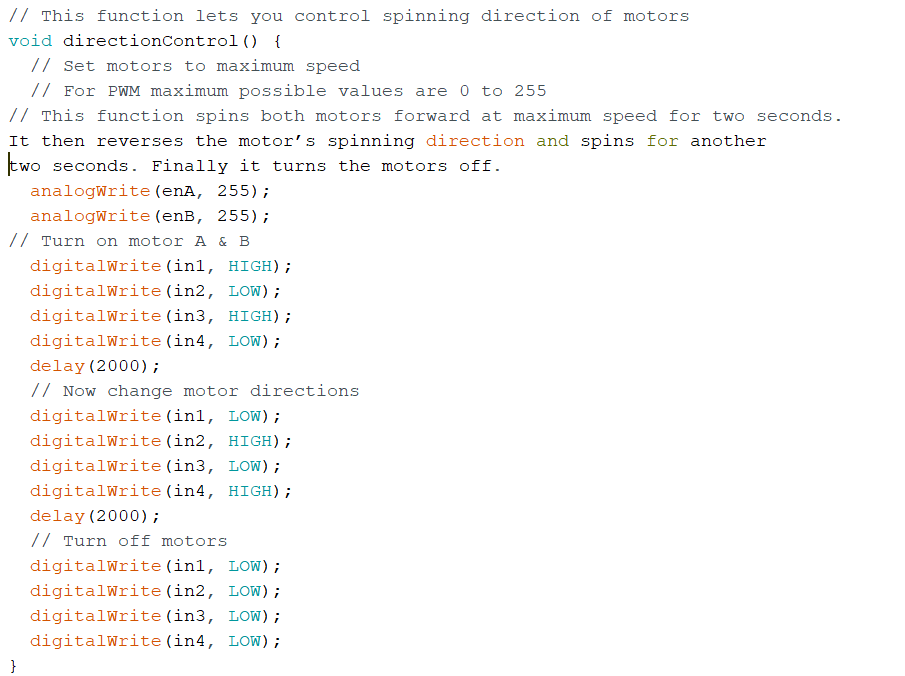
CODE:
TINKERCAD:
Click on ‘create new circuit’ to make a new circuit 🛠.
On the right side, a list of components will be available. Search for ‘Arduino Uno’, ‘DC MOTOR’, Breadboard, Motor driver in that search bar.
Drag and drop in the white open area.
Make the connections as shown in the figure.
Go to the ‘code’ tab from the tabs available to the top right and click on it.
Change the edit mode from blocks to text.
Write the code and click on “Start Simulation”
SERVO MOTOR
Have you ever thought about how a robotic vehicle commonly used in a military application with bomb detention is controlled or how metal cutting and forming machines provide precise motion for milling, lathes, and bending for metal fabrication, or how an antenna positioning system controls the precision in azimuth and elevation?
These servo motor applications are most commonly used in closed-loop systems where precise position control is commonly found in industrial and commercial applications.
WHAT IS A SERVO MOTOR?
A servo motor is a self-contained electrical device that rotates parts of a machine with high efficiency and with great precision.
The output shaft of this motor can be moved to a particular angle, position, and velocity that a regular motor does not have.
The Servo Motor utilizes a regular motor and couples it with a sensor for positional feedback.
The controller is the most important part of the Servo Motor designed and used specifically for this purpose.
The motor is controlled with an electric signal, either analog or digital, which determines the amount of movement which represents the final command position for the shaft. A type of encoder serves as a sensor providing speed and position feedback. This circuitry is built right inside the motor housing which usually is fitted with a gear system.
TYPES OF SERVO MOTOR
Types of Servo Motors are classified into different types based on their application, such as the AC servo motor, and DC servo motor.
There are three main considerations to evaluate servos motors. First based on their current type – AC or DC, and secondly on the type of Commutation used, whether the motor uses brushes and the third type of consideration is the motor's rotating field, the rotor, whether the rotation is synchronous or asynchronous.
APPLICATIONS:
Servo Motor in Robotics:
One of the most popular servo motor applications is in robotics. Consider a simple pick and place robot. A pick and place robot is a robotic machine that is used to pick an object from one position and place the object at a different position (as the name suggests).
Servo Motor Applications in Camera Auto Focus:
The camera autofocus uses a servo motor built into the camera that corrects precisely the position of the lens to sharpen the out-of-focus images.
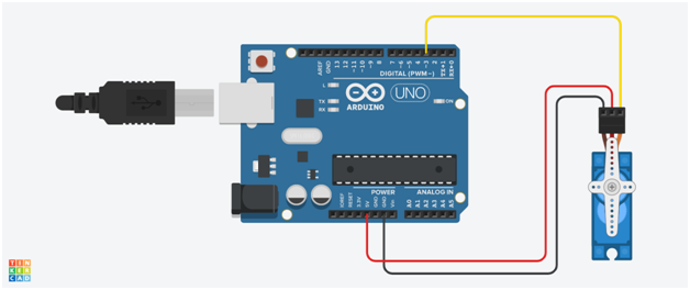
CIRCUIT DIAGRAM:
CODE EXPLANATION:
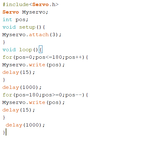
We need to use a library named "Servo. h". This is an inbuilt library with Arduino IDE. There is two way to include a library
Go to Sketch>Include library>Servo
OR
Just type #include<Servo.h>
Next, we need to declare an integer type variable. Let the variable named "pos". This variable can only hold integer values.
In the declaration part, we need to declare another variable. Let the variable name be "Myservo". This variable is used to connect the corresponding servo to the entire code. Here we use the keyword "Servo". The syntax is "Servo variable_name". The code looks like,
Servo myservo;
Every Arduino program consists of a "void setup()" function and "void loop()" function. When we turn on the Arduino the functions/statements in "void setup()" will work first and it will work once. After that, the functions/statements in void loop() will work as a loop.
We need to set the signal pin of the servo motor to Arduino pin In the "void setup()". In the clear voice, Here we are declaring which pin of Arduino to control the servo motor. Here we are using Digital Pin 3 of Arduino to control the servo motor.
Here we use the keyword attach(). The syntax is "variable_name.attach(pin_number)". The code looks like,
Myservo.attach(3);
Let's discuss the servo control statement. The keyword is "write()". and the syntax is "variable_name.write(pos)". We can either use a variable or number which is between 0 and 360 in the write function.
Myservo.write(pos);
Now we need to set a loop function. Here we are using the "for()" loop to control the servo motor. In the for() loop, set the minimum value is 0. ie. (.pos=0) and maximum value is 180. ie. (pos<=180). Then increment the pos ie. (pos++). Then implement the write function(function in Step-6) in the for a loop. Then add a delay function. This delay function helps to wait 15ms for the servo to reach the position.
for(pos=0;pos<=180;pos++){
Myservo.write(pos);
delay(15);
}
Then add another delay function after the for a () loop. This delay function waits for a corresponding time(which is included in the delay function) after the above for loop.
delay(1000);
Now we need to set another loop function. Here we are using the "for()" loop to control the servo motor. In the for() loop, set the minimum value is 180. ie. (.pos=180) and maximum value is 0. ie. (pos>=0). Then decrement the pos ie. (pos--). Then implement the write function(function in Step-6) in the for a loop. Then add a delay function. This delay function helps to wait 15ms for the servo to reach the position.
for(pos=180;pos>=0;pos--){
Myservo.write(pos);
delay(15);
}
Then add another delay function after the for a () loop. This delay function waits for a corresponding time(which is included in the delay function) after the above for loop.
delay(1000);
The code is completed
ARDUINO CODE:
TINKERCAD:
Click on ‘create new circuit’ to make a new circuit 🛠.
On the right side, a list of components will be available. Search for ‘Arduino Uno’ and ‘Servo motor’.
Drag and drop in the white open area.
Make the connections as shown in the figure.
Go to the ‘code’ tab from the tabs available to the top right and click on it.
Change the edit mode from blocks to text.
Write the code and click on “Start Simulation”
Arduino Uno board can drive this servo motor without an additional power supply.
POTENTIOMETER:
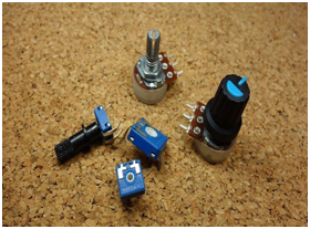
WHAT IS IT?
A potentiometer is a three-terminal resistor where resistance can be manually adjusted to control the current flow.
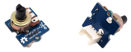
HOW DOES IT WORK?
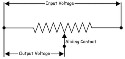
Also known as a potmeter or Pot, it consists of a resistive element called the track and a sliding contact called the wiper internally where end terminals are attached to the resistive element.
Resistance is then adjusted with the manual wiper which is movable and touches a resistive strip of material. When it is moved up closer to terminal 1 and away from terminal 2, resistance is lowered to terminal 1 while resistance is raised at terminal 2 and vice versa.
The input voltage will be applied across the resistor where output voltage will be the drop in voltage between the fixed and sliding contact as shown below.
They are used to accurately measure voltage and help achieve a variable voltage from a fixed-voltage source.
They are passive devices which means they do not need a power supply or additional circuits to function.
Common Examples of Potentiometers are:
Measuring Position on a gaming joystick
Controlling audio equipment using volume controls
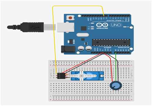
CIRCUIT DIAGRAM:
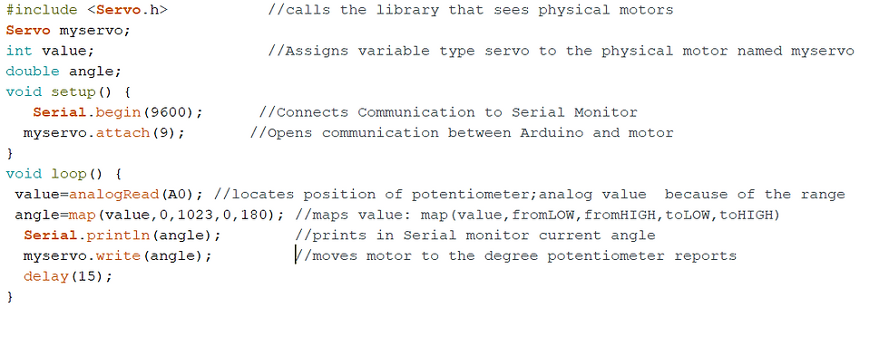
CODE:
TINKERCAD:
Click on ‘create new circuit’ to make a new circuit 🛠.
On the right side, a list of components will be available. Search for ‘Arduino Uno’ ‘Servo motor’ and ‘Potentiometer’.
Drag and drop in the white open area.
Make the connections as shown in the figure.
Go to the ‘code’ tab from the tabs available to the top right and click on it.
Change the edit mode from blocks to text.
Write the code and click on “Start Simulation”
You can see the motor movement to the degree of potentiometer reports.
What are LCD Displays?
An LCD is a thin flat panel, the LCD is an acronym for liquid crystal display. LCDs allow the display of text and images and are often used as part of on-screen navigation and communication.
An OLED is a light-emitting diode that contains thin flexible sheets of an organic electromagnetism material used for visual displays. Essentially, it consumes less power, eco-efficient.
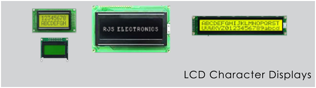
LCD Character Displays
Available in the following sizes:
8×1, 8×2, 16×1, 16×2, 16×4, 20×01, 20×02, 20×04, 24×02, 40×1, 40×2, 40×4
Different color LED backlight is available
Top or bottom viewing angles

LCD Graphic Displays:
Available in the following pixel sizes:
122×32, 128×64, 240×64, 128×128, 250×128
Different color LED backlight is available
Top or bottom viewing
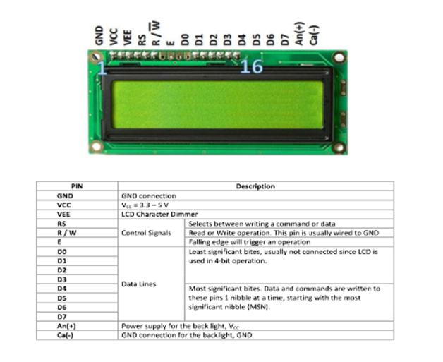
Interfacing of LCD Display to Arduino:
The LiquidCrystal library allows you to control LCD displays that are compatible with the Hitachi HD44780 driver. There are many of them out there, and you can usually tell them by the 16-pin interface.
This example sketch prints "Hello World!" to the LCD and shows the time in seconds since the Arduino was reset.
The Hitachi-compatible LCDs can be controlled in two modes: 4-bit or 8-bit. The 4-bit mode requires seven I/O pins from the Arduino, while the 8-bit mode requires 11 pins. For displaying text on the screen, you can do most everything in 4-bit mode, so an example shows how to control a 16x2 LCD in 4-bit mode.
CIRCUIT DIAGRAM:
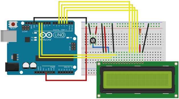
😂 Don’t worry, it’s simple.
ARDUINO CODE:

TINKERCAD:
Click on ‘create new circuit’ to make a new circuit 🛠.
On the right side, a list of components will be available. Search for ‘Arduino Uno’ ‘LCD’ and ‘Potentiometer’.
Drag and drop in the white open area.
Make the connections as shown in the figure.
Go to the ‘code’ tab from the tabs available to the top right and click on it.
Change the edit mode from blocks to text.
Write the code and click on “Start Simulation”
You can see the output on the LCD screen.
Follow us on Instagram for updates, event announcements, and regular quizzes to check your understanding.

Comments